THIS TRAINER IS COMPOSED AS FOLLOWS:
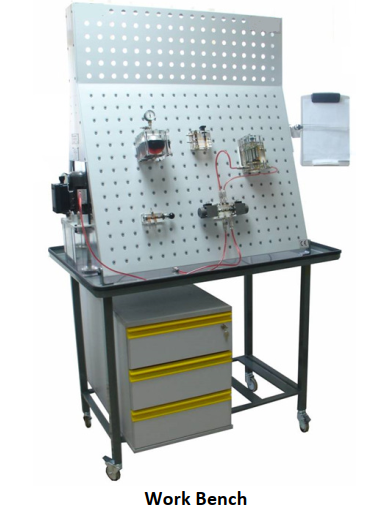
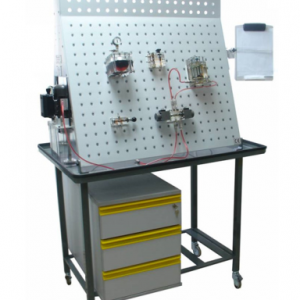
Work bench complete with:
• Metal working panel fully plastic coated;
panel dimensions: 950 x 1050 mm. With Ø5 mm holes every 50mm (horizontally and vertically) for quick clamping of hydraulic components without using additional tools;
• 4 wheels (the 2 front wheels are lockable);
• 3 drawers with locking systems with key for storing components;
• 1 clipboard located on the side of the work bench.
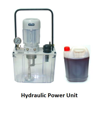
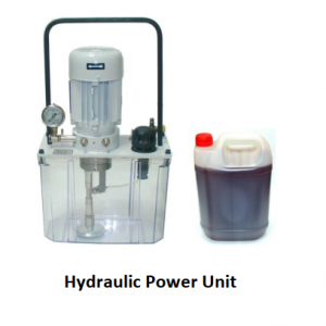
Movable hydraulic power unit.
This electrically powered hydraulic unit consists of:
• 6 litres transparent tank;
• 0.12Kw single-phase motor;
• extra-silent gear pump, Q= 0.5 l/min;
• pressure relief valve, P max: 10 bar;
• pressure gauge: 0-16 bar Stop-Start switch;
• quick fit couplings (1P – 2T);
• 3m power cable with plug;
• tap for inserting bubbles into circulating oil circuit;
• oil can (5 litres) with special red colouring.
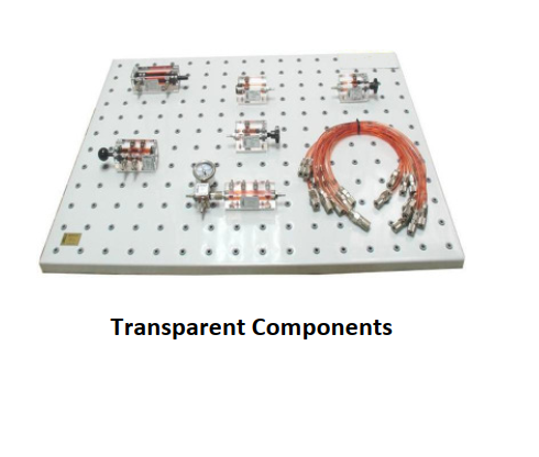
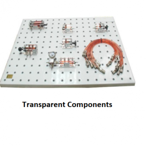
Transparent components:
• Double effect cylinder: d/e cylinder Ø20 x Ø10 x 58mm.
• Manually actuated 4/2 distributor: manually actuated, spring return
• Pressure relief valve: ball valve. Direct control.
• 3 connection divider with pressure gauge: 0-10 bar pressure gauge. One female + two male’s quick fit connectors.
• Check valve: seat check valve.
• Flow restrictor: needle flow restrictor, manual regulation.
• 6 connection divider: 6 male quick-fit self-sealing connectors, size NW4
• Set of hoses: 6 NW3 x 520 mm length, 4 NW3 x 350 mm length. With quick-fit self-sealing female connectors.
• Workbook with theory and practices.
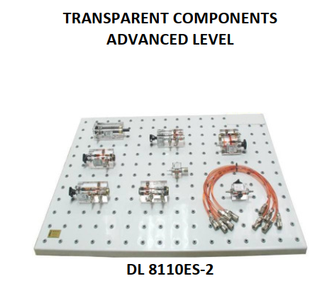
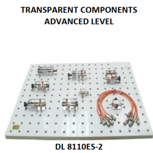
Transparent Components advanced level
• Pressure relief valve with damping: spool valve with damping 3 way valve.
Manual regulation.
• Single effect cylinder: Ø20x Ø10×40 mm. Spring return.
• Pressure reducing valve: 3 way pressure reducing valve. Direct control.
Manual regulation.
• One way flow restrictor: needle valve with by-pass check valve
• Shut off valve: 2/2 valve. Manually actuated.
• Piloted one way restrictor: hydraulically actuated check valve
• Flow control valve with pressure compensation: hydrostatic valve
incorporated. Manual regulation.
• 4 connection divider: 3 male + 1 female quick-fit self- sealing connectors.
• Set of hoses: 5 x 520 mm length. With quick-fit self-sealing female connectors.
• Workbook with theory and practices.
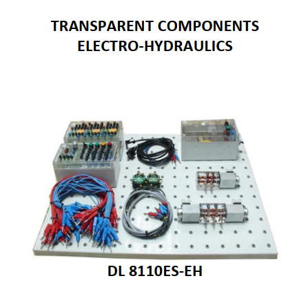
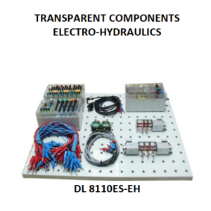
Transparent components electro-hydraulics
• Electrical power supply unit: 220 VAC/24 VDC, I=5 A. Over load and short circuit protection. On/Off switch, On/Off indication lamp, Electronically stabilized, Ø=4 mm quick connectors, Plastic box with printed transparent cover.
• Control unit: 4 push buttons, 2 green, 1 red, 1 yellow, with 1 normally open + 1 normally closed contacts each. 1 switch with 1 normally open + 1 normally closed contacts. 1 connection / disconnection electronic timer, 0 to 6 seconds regulation. 4 spark suppressing diodes. 4 indicator lights, 2 green, 1 red and 1 yellow. Ø=4 mm quick connectors. Plastic box with printed transparent cover.
• Relay unit: 3 relay unit with 4 exchanged (switched) contacts each. On/Off light indicator on every relay solenoid. Spark surprising diode on every solenoid. 6 connection divider for positive voltage. 6 connection divider for negative voltage. Ø=4 mm quick connectors. Plastic box with printed transparent cover.
• Set of connection cables: 14 blue cables, 500 mm length with Ø4 mm male connectors
14 red cables, 500 mm length with Ø4 mm male connectors
8 blue cables, 1500 mm length with Ø4 mm male connectors
8 red cables, 1500 mm length with Ø4 mm male connectors
• Set of 3 connectors for solenoids: 2 grey + 1 black.
Including solenoid 2P+G connector, on/off indicator lamp, cable and male. Ø=4 mm quick connectors.
• 4/2 solenoid valve: Spring return, 24VDC.
• 4/3 solenoid valve: 4/3 valve, spring centered. A, B, P y T closed in central position. 24 VDC solenoids.
• Set of two roller limit switches: 1 normally closed + 1 normally opened contacts. Transparent body. Ø=4 mm female connectors.
• Workbook with theory and practices.


