CIM – Computer Integrated Manufacturing
Computer-Integrated Manufacturing (CIM) is a method of manufacturing in which the entire production process is controlled by computer. Typically, it relies on closed-loop control processes, based on real-time input from sensors.
De Lorenzo’s proposal for CIM automation products is especially designed for engineering graduates. Students can study the theory and work with the system to get a sound knowledge of the CIM, which allows for transversal applications in the following didactic areas: Automation, Pneumatics, Mechatronics, Electronics, Process Control, etc.
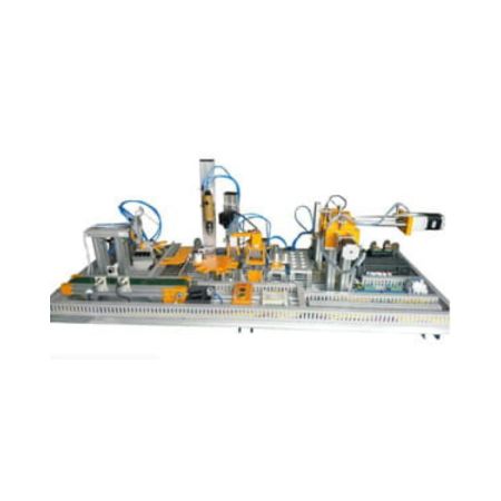
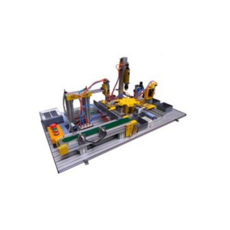
Our system is composed of different modules, each one reproducing a single basic application that is commonly used in the industry.
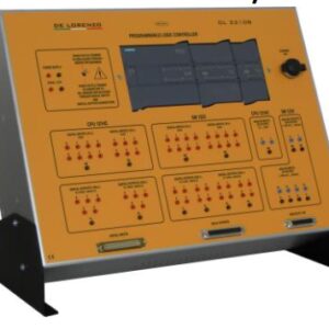
Each module is implemented with real electronics, mechanics and pneumatics components and has a specific function. As an integrated computer system, the output of one activity serves as the input to the next activity, through the chain of events. The whole system is controlled by one Programmable Logic Controller (PLC) and it can be configured to perform a complete process.
The basic modules are the following:
• Conveyor Unit
• Linear Transfer Unit
• Pick and Place Unit
• Six Station Rotary Table
• Vision Inspection System
• Drilling Module
• Unloading Arm
• Weighing Module
• Palletizer Unit


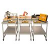
DL CIM-A

DL CIM-B

DL CIM-C
NOTE: A single-phase electro-compressor like the DL 8110SLZ is needed.
CONVEYOR UNIT
 The materials are transferred in a linear motion by means of the belt conveyor driven by geared DC motors. This unit moves materials / objects from one end to the other. Sensors are used to sense the parts material and presence. This is a miniature model of a real industrial conveyor system.
LINEAR TRANSFER UNIT
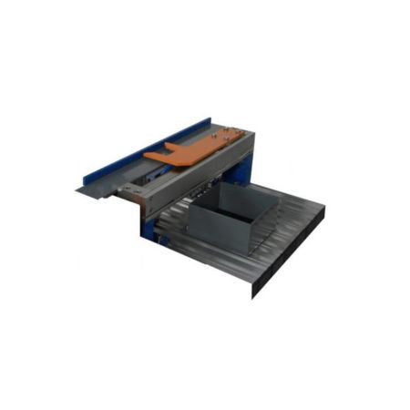
 The Linear Transfer Unit is an electro-pneumatic controlled linear actuator. Magnetic switches are fixed to sense the retracted and extended position of the transfer unit. The Linear Transfer Unit transfers materials from the conveyor to the linear Pick and Place Unit with the help of a pneumatically operated rod less double acting cylinder.
PICK & PLACE UNIT
 The Pick & Place Unit is a totally electro-pneumatic control system. There are three main parts in this unit: a Vertical arm (vertical double acting cylinder), a Horizontal arm (horizontal double acting cylinder) and an Angular gripper (double acting angular gripper for holding work pieces). Magnetic switches are fixed to sense the retracted and extended position of the actuator. The Pick & Place Unit transfers the material from the Linear Transfer Unit end to the next Unit with the help of vertical arm, horizontal arm and angular gripper.
SIX STATION ROTARY TABLE
 A Six Station Rotary Table consists of a horizontal circular worktable, on which the work piece is placed to be processed. The worktable is indexed to present each work piece to each work head to accomplish the sequence of machining operations.
DRILLING MODULE
 The Module simulates the function of drilling the work piece. The PLC tells the vertically double acting flat cylinder to position the drilling device near the work piece and to start the drilling device.
VISION INSPECTION SYSTEM
 The vision system is a compact visual sensing equipment, which is used for quality control inspections in automated production lines. The vision system serves under the class of visual sensing methods. The vision system basically analyzes an image obtained by a video camera, displays it and reports its characteristics to the system controller.
UNLOADING ARM
 The Unloading arm or horizontal Pick & Place Unit is an electro-pneumatic system in which the movement is controlled by a linear and rotary actuator. This system works as a miniature pick and place robot with a limited path application. The Unloading arm is used to transfer the components or work pieces from one workstation to the other.
WEIGHING MODULE
 The Weighing module consists of two elements: the load cell and the interface circuit. The load cell generates a variable resistance value related to the weight of the object that is placed over it. The interface circuit receives, processes and sends this value to the analogue input of the PLC, which determines the correspondent weight of the work piece placed over the load cell.
PALLETIZER UNIT
 The Palletizer is used for palletizing (placing) the work piece in a particular order. Our XY Palletizer is a stepper motor controlled unit. The motor controls the movement and the position of the axis of the Palletizer. For workpiece handling, a suction cup is provided which is con- trolled using a flat cylinder – double acting. The cylinder will extend & retract to pick up or dispense the workpiece.
SOFTWARE
The system includes the software for programming the PLC.
PC is not included.
On request, it can also be supplied with a Supervisory Control And Data Acquisition (SCADA) software and provided with a 7” Human Machine Interface (HMI).
The software interfaces with the CIM’s PLC.
The ordering codes for the CIM versions that include the SCADA software are the following: DL CIM-AS for DL CIM-A
DL CIM-BS for DL CIM-B
DL CIM-CS for DL CIM-C


