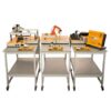
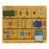
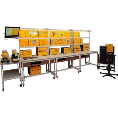
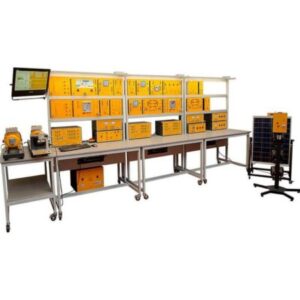
The smart grid system developed by De Lorenzo can be organized in eight subsystems, each comprised of several modules. The first four subsystems are simulations of energy sources; the first one is the main power supply of the grid with a three-phase supply unit that represents a coal plant.
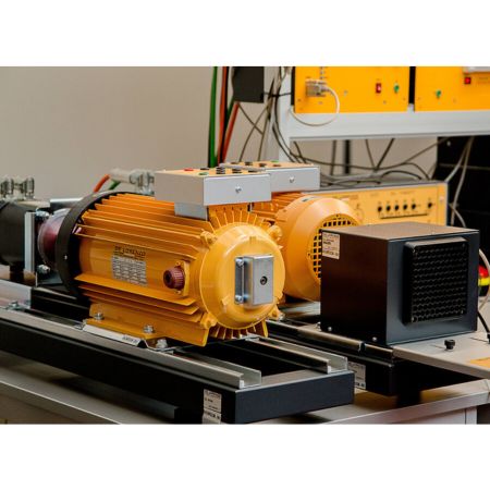
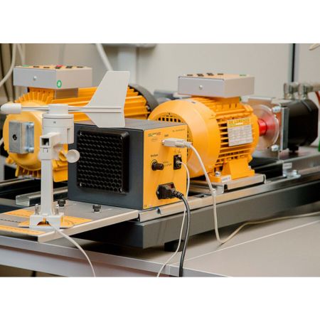
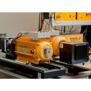
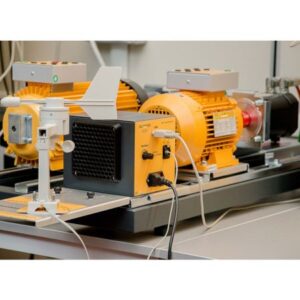
The other three subsystems correspond to alternative sources of energy: wind, hydroelectric and solar. The wind plant simulation is made with a three-phase induction motor acting as a generator while the hydroelectric plant simulation is made with a three-phase synchronous machine, additionally with a generator synchronizing relay module to make possible the connection to the grid. Finally, the solar energy part of the system is generated with a solar panel and four dimmable lamps simulating the sun, which is connected to an inverter module that allows the energy generated to be transferred to the grid
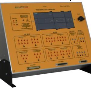
A fifth subsystem in the smart grid consists of modules for fault protection; the modules are a feeder manager relay that measures in real time voltages and currents to detect faults in the grid and four power circuit breakers controlled by the previous module to disconnect faulty lines
The sixth subsystem refers to modules for measuring; it has three maximum demand meters that measure AC voltages, currents, frequencies, active power, reactive power, apparent power, power factor and THD for each of the three available phases in the grid and two electrical power digital measuring units that, besides measuring the same as the previous module, make measurements of DC voltage, current, power and energy.
The seventh subsystem is for power factor control with 2 modules, the first one is a switchable capacitor battery with four different values of capacitors and the second one is a reactive power controller that activates the capacitors of the previous module to make a power factor correctio.
The last subsystem is composed of passive elements; three modules with different kind of loads (capacitive, inductive, resistive) that simulate the loads in a house or factory and two modules with impedances simulating the losses generated in transmission lines, specifically in lines of 10 and 100 km length.
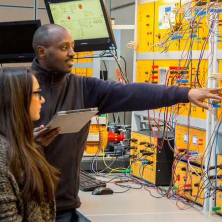
A SCADA software provides to the acquisition and storage of the data coming from the measurement instruments and to the control of the actuators for an “intelligent” management of the whole electrical system. The SCADA software can also be supplied on request in an OPEN version, so that the teacher can implement his own project and select modes and procedure for visualizing the parameters and controlling the actuators.
The system described above represents the basic configuration of our laboratory (DL SGWD).
Optionally, it is also possible to add an additional wind energy small scale generation system, with a real wind turbine connected to an inverter module to make possible the connection to the grid.


