THEORETICAL TOPICS
• Amplitude modulation and demodulation (AM)
• Double side band modulation and demodulation (DSB)
• Single side band modulation and demodulation (SSB)
• Frequency modulation and demodulation (FM)
• Phase modulation and demodulation (PM)
• VCO and PLL circuits
• Carrier generator
• Low frequency generator
• Noise generator
• Fault simulation
TECHNICAL FEATURES
• AM modulation and demodulation
Carrier input 0 – 15 V peak-to-peak, 70 – 700 kHz Modulator input 0 – 15 V peak-to-peak, 3.5 – 50 kHz
• DSB modulation and demodulation
Carrier input 0 – 15 V peak-to-peak, 70 – 700 kHz
Modulator input 0 – 15 V peak-to-peak, 3.5 – 50 kHz
• SSB modulation and demodulation
Selective filter
Carrier input 0 – 15 V peak-to-peak, 300 – 350 kHz
Modulator input 0 – 2 V peak-to-peak, 30 – 50 kHz
SSB demodulator with ACG
• FM modulation and demodulation
Input 1 – 10 V peak-to-peak, 2-5 kHz
Carrier 6-9 MHz
• Quadrature FM modulation and demodulation
Input 1 – 10 V peak-to-peak, 3-5 kHz
• PM modulation and demodulation
Input 1 – 5 V peak-to-peak, 0 – 300 Hz
• VCO and PLL circuits
Input 0 – 4 V peak-to-peak, 0 – 6 kHz
• Carrier generator
– 15 V peak-to-peak, 70 – 700 kHz
• Low frequency generator
– 15 V peak-to-peak, 3.5 – 50 kHz
• Noise generator
• Transmission with class C amplifier
• Gain of the receiver 15 dB
Complete with theoretical and practical manual.
Dimensions of the board: 297x260mm
ANALOGUE SIGNAL TRANSMISSION
The design and construction of electronic circuits to solve practical problems is an essential technique in the fields of electronic engineering and computer engineering.
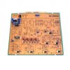
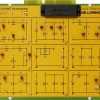
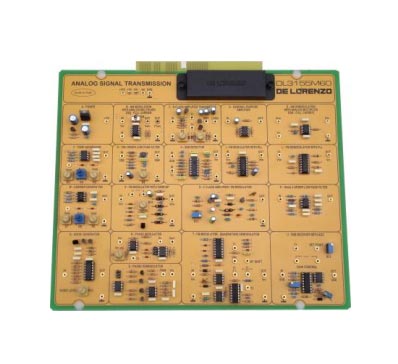
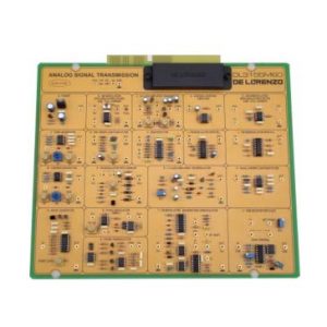
With this board the students can study the operating principles of the most common techniques of analog modulation (AM, DSB, SSB, FM and PM) with the aid also of the signal generators and auxiliary circuits as VCO and PLL.


