THEORETICAL TOPICS
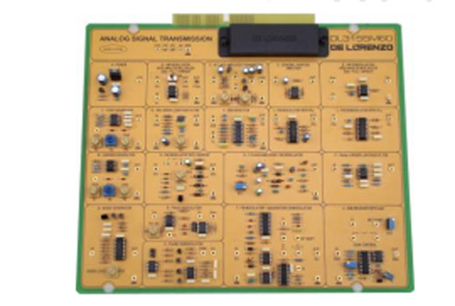
• Amplitude modulation and demodulation (AM)
• Double side band modulation and demodulation (DSB)
• Single side band modulation and demodulation (SSB)
• Frequency modulation and demodulation (FM)
• Phase modulation and demodulation (PM)
• VCO and PLL circuits • Carrier generator
• Low frequency generator
• Noise generator
• Fault simulation
TECHNICAL FEATURES
•AM modulation and demodulation Carrier input 0 – 15 V peak-to-peak, 70 – 700 kHz Modulator input 0 – 15 V peak-to-peak, 3.5 – 50 kHz
•DSB modulation and demodulation Carrier input 0 – 15 V peak-to-peak, 70 – 700 kHz Modulator input 0 – 15 V peak-to-peak, 3.5 – 50 kHz
•SSB modulation and demodulation Selective filter Carrier input 0 – 15 V peak-to-peak, 300 – 350 kHz Modulator input 0 – 2 V peak-to-peak, 30 – 50 kHz SSB demodulator with ACG FM modulation and demodulation Input 1 – 10 V peak-to-peak, 2-5 kHz Carrier 6-9 MHz Quadrature
•FM modulation and demodulation Input 1 – 10 V peak-to-peak, 3-5 kHz PM modulation and demodulation Input 1 – 5 V peak-to-peak, 0 – 300 Hz
• VCO and PLL circuits Input 0 – 4 V peak-to-peak, 0 – 6 kHz
• Carrier generator 0 – 15 V peak-to-peak, 70 – 700 kHz
• Low frequency generator 0 – 15 V peak-to-peak, 3.5 – 50 kHz
• Noise generator
• Transmission with class C amplifier
• Gain of the receiver 15 dB
Complete with theoretical and practical manual. Dimensions of the board: 297x260mm


