THEORETICAL TOPICS
Different types of digital modulation and demodulation for analogue signals Evaluation of pros and the cons of each conversion mode Fault simulation
TECHNICAL FEATURES
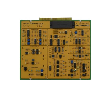
•PCM modulator and demodulator
•8 bit coding with compression, Mµ or A selectable through bridge
•2 channels for transmission and 2 channels for reception
•Possibility to use 1 or 2 digital channels
•Integrated anti‐aliasing and band limiting analogue filters in reception, capacitive switching type
•Passing band from 300 Hz up to 3400 Hz
•PAM signal generation, demodulation, transmission for each single channel
•PAM modulator and demodulator
•Two channel time division
•Regeneration of the synchronism and channel signals
•Sampled, but not quantified signal
•PTM Signal Generation
•Passing band from continuous to 4000Hz
•PWM and PPM modulator and demodulator
•Single channel with passing band from continuous to 4000 Hz
•Regeneration of the synchronism signal
•Conversion of the PWM signal to PPM and from the PPM signal to PWM
•PCM signal generation and demodulation
•PCM Signal Time‐Division Multiplexing
•PFM modulator and demodulator
•Single channel with passing band from 300 Hz to 3400 Hz Circuit realization with the use of a PLL
•Delta modulator and demodulator Single channel with passing band from continuous to 3400 Hz Timing Ramp signal generation Channel noise Possibility to adjust the noise that is superimposed to both analogue and digital signals
• Analogue filters 2 analogue filters with 3400 Hz limited band •Output amplifier 2 amplifiers able to pilot a small loudspeaker
•Microphone amplifier
•Microphoneamplifier with automatic gain control Channel bandwidth
Complete with theoretical and practical manual.
Dimensions of the board: 297x260mm


