THEORETICAL TOPICS
• Definition and characteristics of a combinatory logic network
• The BCD code
• DEC/BCD and BCD/DEC code converters
• Encoders
• Decoders
• Multiplexer
• Demultiplexer
• Parity
• Parity logic circuits
• Nine bit 74180 parity generator/detector
• Unipolar codes
• Bipolar codes
• A/D converters
• Staircase A/D converter
• ADC converter of parallel or flash type
• ADC converter with simple slope
• ADC converter with double slope
• D/A converters (DAC)
• D/A converter with weighed resistances
• D/A converter with R–2R network
• 4 bit asynchronous binary counter
• 4 bit synchronous binary counter
• Asynchronous decimal counter
• Synchronous decimal counter
• Up/down synchronous counters
• Adders
• Half adder
• Full adder
• Parallel binary adders – four‐bit adder
• Quantity comparators
• Four‐bit comparator
• Definition and classification of shift registers
• Operation principle
• 4 bit bi‐directional shift registers
• Applications
• Fault simulation
CIRCUIT BLOCKS
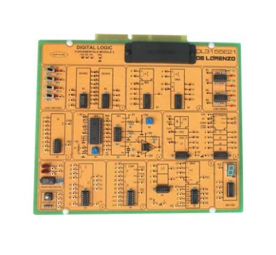
• BCD Decimal Decoder / BCD Priority Encoder
• ADC / DAC
• Multiplexer / Demultiplexer
• 7‐Segment Driver / Display
• Parity Generator / Checker
In addition, the Circuit Board includes the following:
• +5 V regulated supply
• Built‐in clock circuit
• Built‐in pulse generator circuit
• Built‐in counter circuitry
• The 74LS42 decoder and LS147 encoder
• AD673 ADC and AD558 DAC
• The LS151 multiplexer and LS155 demultiplexer
• The LS280 7‐Segment decoder / driver
Complete with theoretical and practical manual.
Dimensions of the board: 297x260mm
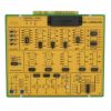
DIGITAL LOGIC FUNDAMENTALS 2
The design and construction of electronic circuits to solve practical problems is an essential technique in the fields of electronic engineering and computer engineering.
With this board the students can study the characteristics of a combinatory logic network using devices such as encoders and decoders, multiplexer and demultiplexers, D/A and A/D converters, parity controllers, BCD/DEC converters, counters, comparators, shift registers and adders.


