TECHNICAL FEATURES
The trainer is composed of the following main components:
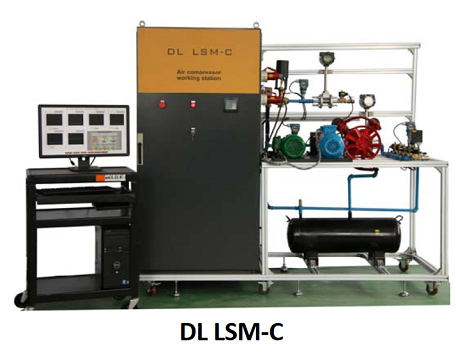
A workbench, complete with loads, motors and data acquisition systems. Approximate dimensions: 2000 mm x 800 mm x 1700 mm (h).
A control panel, with all the electric and electronic components arranged in an ergonomic way.
An auxiliary table for PC, bench‐top instruments and equipment like oscilloscopes, multi meters, etc.
2 Motors (conventional and high efficiency, 1.5 HP).
Load module
Motors driving systems: frequency inverter, soft‐starter, contactor.
Driving system and protection elements such as: circuit breakers, regulators, switches, keys, lights.
Measurement system for complete power parameters.
Mechanical and electrical data acquisition instruments.
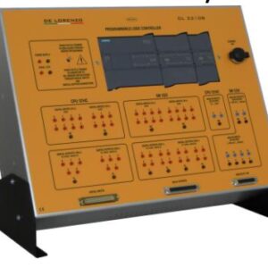
Programmable Logic Controller (PLC).
SCADA Software for supervision and data acquisition.
COMMUNICATION
The communication of the Multifunction Energy Meter with the PLC is made through a serial interface with Mod Bus protocol and all the parameters (historical, time curve, etc.) are shown and monitored on a suitable window of the supervision software.
Also the selection of the motors drive system is made through the supervision software.
The PLC controls the driving systems, collects the parameters from the sensors, the transmitters and the data acquisition devices through digital input/outputs and Mod Bus port communication and communicates with the supervision software through Ethernet.
SYSTEM OPERATION
The student has the possibility to easily select which motor (conventional or high efficiency) will be coupled to the load.
The motor is driven by:
• Frequency inverter or
• Soft start key or
• Direct start by contactors intercalated and controlled by the user through the supervisory software.
TECHNICAL CHARACTERISTICS
The load system of this bench is composed of a two piston air compressor, with 1.5 HP motor capacity. The air compressed tank has a capacity of up to 40 liters, regulated by an electric valve that controls the air pressure of the tank through the supervision software. Additionally, the tank has a safety valve specified in agreement with the conditions of the tank’s capabilities.
The coupling of the motors with the compressor is made of pulleys and belts in “V” shape. The air piping allows the simulation of the load losses through holes of different diameters (5 holes), selected by solenoid type valves and activated by the supervision software. 5 different loads can be adjusted according to the experimental needs timely. The location of these holes allows the measurement of these losses.
The load allows a variation, controlled by the supervision software, from 0 to 120% of the nominal load of the motor.
Each motor (conventional and of high‐efficiency) has a PT‐100 temperature sensor in the carcass and in each stator coil that allows the monitoring of this parameter through the supervision software.
The torque and rotation transducers are installed in the load axes to avoid to be moved when changing motors.
All of the electrical connections for motors input power and sensors are made with fast connectors that allow for a rapid change of the motors and also protect against possible inversion of polarity.
MEASUREMENT SYSTEM
The measurement system of the input power is composed of a Multifunction Energy Meter that measures:
Phase‐phase and phase‐neutral voltage.
Current, active, reactive and apparent power.
Three‐phase and single‐phase power factor.
Frequency and active and reactive energy.
OTHER FEATURES
The main devices, Frequency Inverter, Soft‐Starter Key, PLC and the Multifunction Energy Meter, are assembled in a didactic and ergonomic way; they are visible and easily accessible.
Shunt resistors are installed in the inputs and outputs of the driving systems, to allow for reading the current signals through an oscilloscope.
The PLC is programmed in SFC, LADDER, FBD, SL and IL language.
The instrumentation as well as the driving systems and the motors are fully industrial; in other words, the equipment used (sensors, meters, driving systems, inspection tools, etc.) are designed for industrial use, commercially available and listed in the catalogues of their respective manufacturers.
LIST OF EXPERIMENTS
It is possible to perform a large number of practical experiments such as:
Study of the energy efficiency of the motors for a 0 to 120% variation of the load.
Study of energy efficiency of the motors as a function of the use of the frequency inverter application, through the variation of the speed of the motor‐load combination.
Generation of the characteristic curves of the main devices (electrical and mechanical parameters, pumps, fans, etc.).
Generation of the characteristic curves of the motors (conventional and high efficiency).
Comparison of the electrical and mechanical values from direct driving, soft start and frequency inverter as a function of the variation of the load.
Comparison of the consumption of energy for different configurations and types of devices.
Analysis of the energy efficiency considering different setups in the coupling between the motor and the load.
SOFTWARE
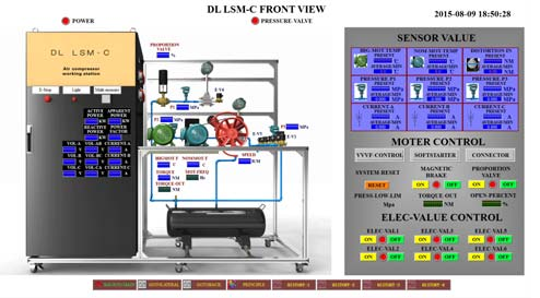
The Supervising Software uses 3D stereoscopic images and shows historical curves and real‐time curves; the screen interface includes operation buttons and graphs with the acquired data.
The supervision software has a main window with the schematic drawing of the process and each element of the Working Station has a shortcut for their corresponding monitoring window. The main components shown in the software’s window are “animated” when active.
Each sensor, transducer, and transmitter has its own window with a graphical representation of the component, showing its numeric value and average measurement.
Each measuring element, driver and load system has its own window. These windows supply real‐time data, provided by the electrical and mechanical sensors.


