TECHNICAL FEATURES
The trainer is composed of the following main components:
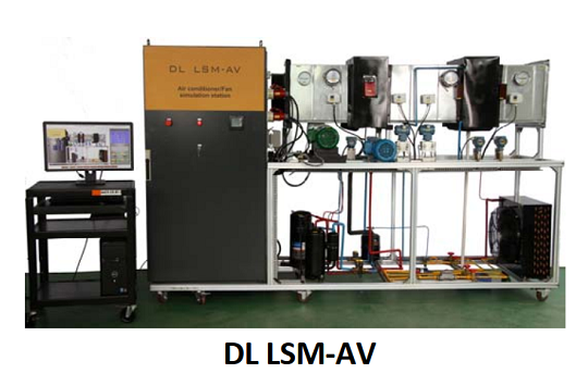
A workbench, complete with loads, motors and data acquisition systems. Approximate dimensions: 2800 mm x 800 mm x 1700 mm (h).
A control panel, with all the electric and electronic components arranged in an ergonomic way.
An auxiliary table for PC, bench‐top instruments and equipment like oscilloscope, multi meters, etc.
2 Motors (conventional and high efficiency, 1.5 HP).
Load module.
Motors driving systems: frequency inverter, soft‐starter, contactor.
Driving system and protection elements such as: circuit breakers, regulators, switches, keys, lights.
Measurement system for complete power parameters.
Mechanical measurement transducers.
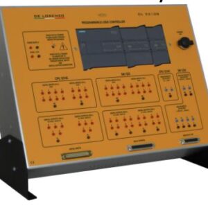
Programmable Logic Controller (PLC).
SCADA Software for supervision and data acquisition.
COMMUNICATION
The communication of the Multifunction Energy Meter with the PLC is made through a serial interface with Mod Bus protocol and all the parameters (historical, time curve, etc.) are shown and monitored on a suitable window of the supervision software.
Also the selection of the motors drive system is made through the supervision software.
The PLC controls the driving systems, collects the parameters from the sensors, the transmitters and the data acquisition devices through digital input/outputs and Mod Bus port communication and communicates with the supervision software through Ethernet.
SYSTEM OPERATION
The student has the possibility to easily select which motor (conventional or high efficiency) will be coupled to the load.
The motor is driven by:
• Frequency inverter or
• Soft start key or
• Direct start by contactors intercalated and controlled by the user through the supervisory software.
TECHNICAL CHARACTERISTICS
One of the load systems of this station is a centrifugal fan and an axial fan, these fans are coupled to the same air tube. Parallel operation of the fans is possible, since they are placed in a “Y” format at the left end of the air tube. The conventional and high‐efficiency motors can be alternated from the fans through direct joining of a metal connector.
An electric damper is installed in the air tube, controlled by the PLC, allowing the control of the air flow through the Supervising Software.
An air flow and speed transducer is installed in the air tube, after the fans; it allows checking this parameter and the performance of the damper seeking to decrease or to increase or even to block this output. All of these functions are monitored and controlled by the Supervising Software.
Another load of this trainer is a complete air conditioning system.
With the purpose of allowing the study and the performance of different types of compressors for air conditioning, this system has one hermetic type piston compressor and another compressor of the same capacity, but of the “SCROLL” type.
The SCROLL compressor is driven by a frequency inverter controlled by the PLC of the trainer to allow the speed variation of the compressor and consequently its performance.
The air conditioning system has all the components; the compressors are dimensioned for a 20.000 BTU capacity.
The two compressors are linked in parallel. Between them there are 4 solenoid valves, NF type, actuated by a specific window in the supervision software, making possible to operate one or the other compressor, separately, in the same system.
The air conditioning evaporator system is installed in the air tube of the system of ventilation of the workbench, after the damper, and it is dimensioned in agreement with this tube and the refrigerating capacity of the system.
Also, in the air tube there are two heating resistors, shield for evaporator defrost and for air heating at the output of the tube.
A suitable tray is installed at the bottom of the tube, after the fans to be a moistness system. An appropriate receiving box is also needed.
The piping system of the air conditioning is made of copper, with welded junctions, and it has the following gauges: 1/2″ for the discharge circuit and 5/8″ for the suction circuit. It is painted with synthetic ink in blue colour.
The following equipment are installed in the compressors output: a condensing unit with ventilation; a drying filter for the system capacity; one humidity viewfinder; a flowmeter, also with “by‐pass” circuit made of manual sphere valves.
A liquid receiving container is installed in the loop.
A sight glass is installed in the loop.
A flowmeter is installed in the loop.
The following equipment are installed in the piping: a capillary tube and an expansion valve connected in parallel, having between them 2 manual sphere valves, to allow selecting which circuit of the two components.
Other accessory components as filters complete the system for functional and didactic study of the cooling systems.
SOFTWARE
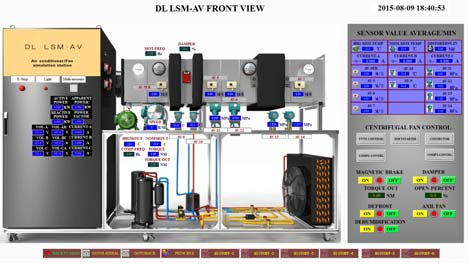
The Supervising Software uses 3D stereoscopic images and shows historical curves and real‐time curves; the screen interface includes operation buttons and graphs with the acquired data.
The supervision software has a main window with the schematic drawing of the process and each element of the Working Station has a shortcut for their corresponding monitoring window. The main components shown in the software’s window are “animated” when active.
Each sensor, transducer, and transmitter has its own window with a graphical representation of the component, showing its numeric value and average measurement.
Each measuring element, driver and load system has its own window. These windows supply real‐time data, provided by the electrical and mechanical sensors.
MEASUREMENT SYSTEM
The temperature and the pressure at the output of the compressors are measured through a temperature transmitter and a pressure transmitter, both with local display. These two parameters are monitored in real time by the supervision software, in a specific window.
The measurement system of the input power is composed of a Multifunction Energy Meter that measures:
Phase‐phase and phase‐neutral voltage.
Current, active, reactive and apparent power.
Three‐phase and single‐phase power factor.
Frequency and active and reactive energy.
OTHER FEATURES
The main devices, frequency Inverter, soft‐starter key, PLC and the Multifunction Energy Meter, are assembled in a didactic and ergonomic way; they are visible and easily accessible.
Shunt resistors are installed in the inputs and outputs of the driving systems, to allow for reading the current signals through an oscilloscope.
The PLC is programmed in SFC, LADDER, FBD, SL and IL language.
The instrumentation as well as the driving system and motors are fully industrial; in other words, the equipment used (sensors, meters, driving systems, inspection tools, etc.) are designed for industrial use, commercially available and listed in the catalogues of their respective manufacturers.


