TRAINING OBJECTIVES
• Study of a forced vortex
• Study of a free vortex
TECHNICAL DATA
Tank:
• Material: methacrylate.
• Cylindrical tank: Ø250 x 180 mm
• Inner diameter tank: Ø244 mm
Inlet flow nozzle:
• Free vortex nozzle:
– Inner Ø= 12.5mm
– Inclination angle rod: 15°
• Forced vortex nozzle:
– Inner Ø= 6mm
– Inclination angle rod: 60
Accessories:
• Vertical rods for height measurement.
– Rods: Ø 6mm
– Rod length: L=320mm
– Radial rod position: 110, 90, 70, 50 and 30mm
• Pitot tubes:
– Length radius: 15, 25 and 30mm
– Inner Ø= 1mm
• Caliber
– Range= 20 – 120mm
• Outlet nozzle:
– Diameters: Ø8mm, Ø16mm and Ø24mm
FREE AND FORCED VORTICES
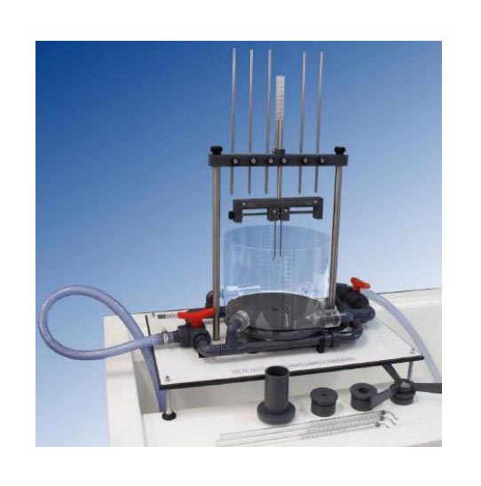
The objective of this trainer is study of the formation of free and forced vortices.
It is called forced vortex when the rotation of a fluid it moves as a solid respect to an axis.
By definition, in this kind of vortex, each particle has the same angular velocity.
It is possible to create a forced vortex with an inlet water supply through nozzles, which at a certain inclination, they start a propeller like movement. This propeller rotates the fluid forming a parabolic curve.
Once the vortex has been generated, it may be represented with measuring rods.
These allow measuring the height of the parabolic curve at each point at a fixed radial distance.
The free vortex is one of the basic types of rotational flow.
This movement can be distinguished from the forced vortex because each particle moves in a circular path at different speed rates.
This variation is inversely proportional to the distance from the center of rotation. A pair of nozzles will be responsible of getting the fluid into the reservoir.
Their inclination allows free vortex formation.
It can be measured by different outlet nozzles the influence of the nozzle diameter with the characteristics of the vortex, as well as the pitot tubes of different lengths, in order to make pressure readings at different depths.
Furthermore a caliber can do readings of the vortex diameter according to its depth, thereof it is possible to represent a graphic of the result.
In order to make an appropriate observation of the vortex in each experiment, the flow control can be set by a discharge valve on the hydraulic bench, as inlet, and a ball valve as outlet.


