TRAINING OBJECTIVES
• Determination of the loss of primary load produced in a pipe with a laminar flow.
• Determination of the loss of primary load produced in a pipe with a turbulent flow.
TECHNICAL DATA
• Load tank= Ø 150mm height= 500mm long.
• Maximum load for laminar flow: 900mm.
• Inner pipe Ø= 3mm
• Length among outlets= 500mm
• Water column measuring range= 600mm
• Differential digital manometer measuring range = 2000mbar.
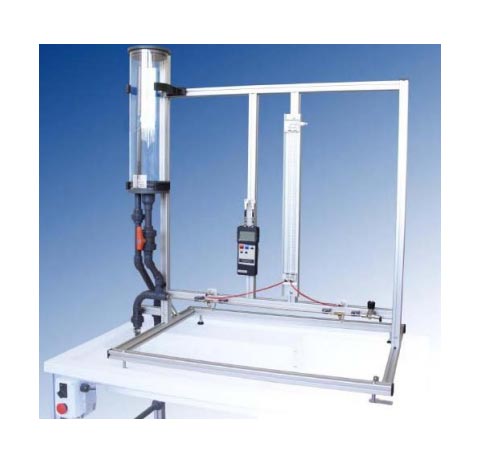
FRICTION IN PIPES UNIT
The objective of this system is the study of primary load losses that occur along a pipeline, both laminar and turbulent flows.
This unit has a horizontal pipe, in which readings of the pressure loss produced at different flow rates can be performed.
It is also possible to study friction with a turbulent or laminar flow.
To achieve the latter, pipe can be fed from a reservoir of constant height.
For readings of pressure upstream and downstream in the test pipe, we have two differential pressure gauges, one with water and other with mercury.
Two flow valves can be used for regulation: one located at the beginning of the installation and the other located at the end of the test pipe.
The flow through the pipe is measured by using the volumetric tank of the hydraulic bench.


