TRAINING OBJECTIVES
• Measure and check of main pressure losses in straight segments of many kinds of pipes.
Possibility to test pressure losses in:
– Two different inner diameter pipes: 21.2 and 13.6mm
– Different materials testing.
• The proof of relation between pressure losses and speed flow in a pipe.
• Roughness measurement in pipes:
– Galvanized steel
– Cooper
– Etc.
• Measurement and check of secondary pressure losses in installation components. Possibility to test pressure losses in:
– Short radius 90° elbow
– Large radius 90° elbow o 45° elbow
– Tee o Bent tee
– Abrupt reduction
– Abrupt widening
– Smooth reduction
– Plug valve
– Check valve
– Seat valve
– Ball valve
– Diaphragm valve
– Diaphragm
– Venturi pipe
– Rotameter
– Filter
– Etc.
• Determination of loss Coefficient “K” corresponding to each component listed above.
• Utilization, determination and tare of many metering elements such as:
– Rotameter
– Venturi pipe
– Diaphragms: inner diameter 15mm and 13mm
– Flow meter valve
– Etc.
• Working pressure tests along the installation
• Employment of some kinds of pressure gauges
– Water column
– Digital differential pressure gauges
– Bourdon type
• Plot of characteristic pump curve.
TECHNICAL DATA
Inner diameters:
• Main piping: inner diameter = 21.2mm; outer diameter = 25mm
• Reduction/ smooth widening. o Inner Ø = 13.8 mm ; outer Ø = 16mm
. • Reduction/ abrupt widening o Inner Ø = 45.2 mm ; outer Ø = 50mm.
Pressure gauges
• Water column pressure gauge, measure range 1m water column
• Digital differential pressure gauges (± 7000mbar)
• Bourdon manometer, measure range 0 / 25m water column
Bourdon vacuum gauge, measure range -76 cm Hg / 25 m water column
Distance between pressure test points:
• For straight segments 1m distance between n° 7 and n° 14
• 0.5 m between segment n° 12
• Between measuring point and any accessory, there are 40mm, except the following cases:
* Measuring point at 135mm under o above diaphragm (3)
* Measuring point at 125mm abrupt widening upstream (9) and abrupt narrowing downstream (3).
* Measuring point at 270mm smooth widening and narrowing (4/7).
Venturi
• Constrictor inner Ø 12mm
• Pipe inner Ø 21.2mm
• Outlet cone 7°
• Inlet cone 21°
Diaphragm 15
• Constrictor inner Ø 15mm
• Pipe inner Ø 21.2mm
Diaphragm 13
• Constrictor inner Ø 13mm
• Pipe inner Ø 21.2mm
LOSSES IN PIPES
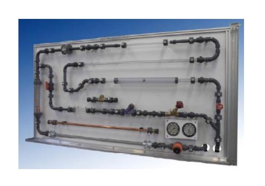
This training equipment has been designed for the study of friction losses in pipes and losses in hydraulic elements such as: valves, metering elements, accessories, etc.
This trainer has been designed to be very flexible, so it allows to hook up new accessories and straight segments of pipes of different materials and roughness.
The piping replacing is quick and simple by using quick fittings.
The user just has to remove the desired segment by unscrewing it and fix another one.
At the bottom of the panel, the trainer has a dripping pan, to collect the residual water that could remain in the piping, keeping the working area and adjacent components dry.
Cleaning labor could be done by students at the end of each practice.
In order to avoid water leaks, the trainer has ecological pressure taps, so during connection or disconnections, they will not cause water losses since they are self-sealing.
This equipment can be attached to the hydraulic bench or to the hydraulic group with flow meter.


